
Lea's Chemistry of Cement and Concrete, Fifth Edition, examines the suitability and durability of different types of cements and concretes, their manufacturing techniques and the role that aggregates and additives play in achieving concrete's full potential of delivering a highquality, longlasting, competitive and sustainable product.
Electrician Circuit Drawings and Wiring Diagrams Youth Explore Trades Skills 3 Pictorial diagram: a diagram that represents the elements of a system using abstract, graphic drawings or realistic pictures. Schematic diagram: a diagram that uses lines to represent the wires .
(1) Make sure that wiring operation is properly done in line with a terminal wire diagram of section 35. (2) Choose a suitable compensation lead wi re in the case of thermocouple input. (3) In the case of resistance bulb input, resist ance value of each lead wire must be less than 5Ω and that of three lead wires must be equal.
· Mack WIRING DIAGRAM − OM (MRU) 2014 – : : Download: Mack WIRING DIAGRAM − TYPE OM : 5Mb: Download: Mack WIRING DIAGRAM − TYPE OM WOBD : : Download: Mack WIRING DIAGRAM − TYPE−OL : : Download: WIRE DIAGRAM−CONVENTIONAL, 12V MACK, : : Download: WIRING DIAGRAM .

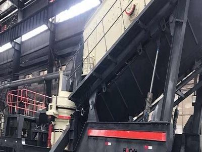
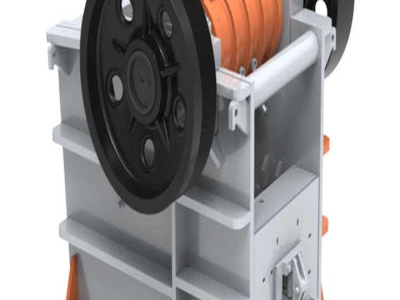
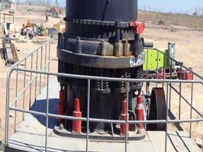
Cement milling. The clinker is ground by differentsize steel balls while it works its way through the mill's two chambers, with gypsum being added to extend cement setting times. 10. Cement .

Besides kg of Portland cement clinker, an input of kg gypsum (not balanced, origin from flue gas desulphurization), kg additional milling substances (not balanced as it is taken as waste without environmental burdens, dust from the cement rotary kiln, fly ash, silica dust, limestone) and × 10 ‒4 kg ethylene glycol (process material for grinding) is taken into ...

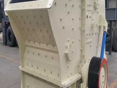
3. Milling • Milling – A machine operation in which a work part is fed past a rotating cylindrical tool with multiple edges. (milling machine) • Types – Peripheral milling • Slab, slotting, side and straddle milling • Up Milling (Conventional) down milling (Climb) – Facing milling • Conventional face, Partial face, End ...

These diagrams are current at the time of publiion, check the wiring diagram supplied with the motor. These diagrams mainly apply to EXTERNAL ROTOR MOTORSbut some standard frame induction motor diagrams have been included for ease of .
· Apr 14, · An NVR switch stands for No Voltage Release. The start button energizes the motor And a magnetic latch in the switch mechanism. The magnetic latch keeps the switch closed until you press the stop button which deenergizes the magnetic coil and opens the contacts. Jan 01, · You would be better off using the NVR switch for safety reasons.
3 Way Switch Wiring Diagram. Take a closer look at a 3 way switch wiring diagram. Pick the diagram that is most like the scenario you are in and see if you can wire your switch! This might seem intimidating, but it does not have to be. With these diagrams below it will take the guess work out of wiring.

· 5. Cover the wire mesh with another layer of concrete and smooth it with a trowel. Pour or shovel another 2 in ( cm) of concrete over the chicken wire. Use a hand trowel to smooth it out evenly. 2 in ( cm) is the recommended thickness for the concrete so it .

WIRE CUTTING MACHINE : Hello friendsI have made a Automatic wire cutting machine using Arduino nano controller there are 3 process level of this machine like1) first process is InputInput like wire length and wire quantity provided by pressing push button .
· States. The balance of domestic cement production is primarily masonry cement. Both of these materials are produced in portland cement manufacturing plants. A diagram of the process, which encompasses production of both portland and masonry cement, is shown in Figure As shown
· It shows how the electrical wires are interconnected and can also show where fixtures and components may be connected to the system. A circuit diagram electrical diagram elementary diagram electronic schematic is a graphical representation of an electrical circuita pictorial circuit diagram uses simple images of components while a schematic diagram shows the components and .
Easy to Build CNC Mill Stepper Motor and Driver Circuits: This is a follow up to the Easy to Build Desk Top 3 Axis CNC Milling Machine Once you get the machine all put together its time to make it go. So it's time to drive the motors. And here I've put together a circuit that I think is the absolu.
TERMINAL MARKINGS AND INTERNAL WIRING DIAGRAMS SINGLE PHASE AND POLYPHASE MOTORS MEETING NEMA STANDARDS See Fig. 211 in which vector 1 is 120 degrees in advance of vector 2 and the phase sequence is 1, 2, 3. (See MG )* MG Direction Of Rotation

ReWiring the stator. First up, the old 42 pole conversion. The 42 pole stators are still the most common and easiest to source. Click on the image to see the full size diagram. At right is a diagram .
ELECTRONICS DIAGRAMS USAS 1966 USA STANDARD APPROVED includes the following: 151 Scope 152 Definitions 153 General Infonnation 154 SingleLine Diagrams, General 155 SingleLine Diagrams (Electronics and Communiions) 156 SingleLine Diagrams (Power Switchgear and Industrial Control) 157 Schematic Diagrams, General
· Appliion Overview: Wire Drawing. The process of wire drawing has in effect changed very little over the years. It uses a combination of a die and/or a series of dies to draw wire to a selected gauge. Drawn wire is in many appliions beyond what we normally would think like electrical wire and TV cables. Mar 4th, 2013.